
Best Practices for Loop Checks That Protect Uptime
A loop check is often treated as a final commissioning task, yet it is one of the clearest opportunities to prevent a start-up delay, process upset, or unsafe control response. The best practices for loop checks begin well before a technician applies a signal at the field device. They depend on accurate drawings, defined test boundaries, qualified personnel, and disciplined documentation from field to control room.
For industrial facilities, a completed loop check provides evidence that an instrument, its associated wiring, marshalling, input/output channel, control logic, display, alarm, and final element respond as intended. It does not replace calibration, functional safety testing, or a full cause-and-effect review. It confirms that the complete signal path works correctly and that the installed system matches the approved design.
Why Loop Checks Require More Than a Signal Test
A loop can appear healthy while concealing a condition that will create operational risk later. A transmitter may be calibrated but landed on the wrong input. A valve positioner may stroke, but in the wrong direction. An alarm may display correctly at the operator workstation while its setpoint, priority, or shutdown action remains unverified.
The practical purpose of a loop check is to prove the path and the response. This includes checking tag identity, polarity, terminations, range, engineering units, scaling, indication, alarm behaviour, and output action where applicable. The depth of testing should reflect the application. A non-critical local indication loop does not require the same level of review as a burner management, emergency shutdown, custody transfer, or high-consequence pressure-control loop.
That distinction matters when planning labour and schedule. Compressing all loop checks into a final shift before start-up may look efficient, but it usually transfers unresolved construction, configuration, and documentation issues into the highest-risk stage of the project.
Best Practices for Loop Checks Start With Preparation
Successful testing starts with a controlled work package. The technician should have the current approved loop drawing, wiring diagram, instrument data sheet, input/output list, control narrative, and applicable cause-and-effect documentation. When drawings are marked up in the field, those changes need a clear process for review and incorporation. Testing against an obsolete revision can create as many problems as testing without documentation.
Before beginning, confirm the loop’s physical boundaries and the responsible parties. Field instrument work, electrical terminations, automation configuration, operations authorization, and vendor support can involve different teams. A short pre-job discussion establishes who is applying the signal, who is observing the control system response, how communication will occur, and who has authority to stop the test.
Safety controls must be specific to the equipment and operating condition. Verify isolation requirements, energy sources, permits, lockout procedures, hazardous-area restrictions, and the potential consequences of actuating a final element. For an in-service facility, placing a loop in test or bypass may require operations approval and a defined restoration step. A bypass that is not logged, communicated, and removed is not a minor administrative concern. It is an operational risk.
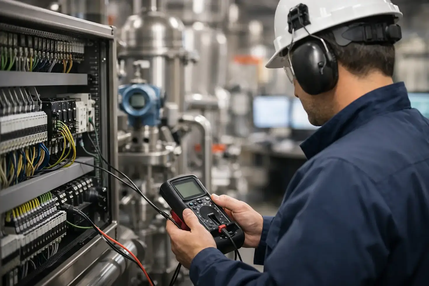
Test equipment should be suitable for the signal and the accuracy required. Calibrated pressure sources, temperature simulators, milliamp sources, loop calibrators, communicators, and multimeters each have a role. Confirm the equipment’s calibration status before use. The reading on the test device is part of the evidence supporting the result.
Verify the Field Device Before Chasing the Signal
Begin at the field device and confirm that the tag, service, range, and installation match the documentation. Check that impulse lines, sensing elements, manifolds, cable glands, shielding, grounding, and terminations are appropriate for the application. A clean signal at the control system does not prove that the process connection is installed correctly.
For analogue loops, test a meaningful number of points across the operating range. A common approach is to verify low, mid-range, and high values, with additional points where project requirements or criticality warrant them. Confirm both the applied value and the value displayed in the control system. Compare them against the expected engineering units and tolerance, not simply whether the number appears to move.
Digital protocols require the same discipline, even though the method differs. Confirm device identification, communications status, configured variables, diagnostic status, and the correct mapping of the intended process variable to the control system. A device can communicate successfully while delivering the wrong variable, range, or status interpretation.
For discrete devices, prove both normal and abnormal states. Verify normally open and normally closed logic against the drawings, then confirm the control system receives the correct state and reacts as intended. Where a switch or contact is safety-related, test requirements may be governed by a separate approved procedure. Do not treat a routine loop check as a substitute for that formal test.
Follow the Signal Into the Control System
At the panel, marshalling cabinet, and control system, inspect the details that are easy to miss under schedule pressure. Confirm terminal numbers, wire identification, shield continuity and termination method, fuse status, power supply, isolators, barriers, and input/output card channels. A reversed pair, incorrect jumper, missing shield connection, or swapped terminal can create intermittent failures that are difficult to diagnose after handover.
The control-room witness should verify more than a displayed value. Depending on the loop, the test should confirm scaling, units, quality or fault indication, alarm setpoints, alarm priority, trends, control faceplates, interlocks, and historian tags. If the loop drives an output, verify the expected response at the final element and confirm the action is correct for both increasing and decreasing signal.
Valve loops deserve particular attention. Confirm the command reaches the correct valve, the valve moves in the correct direction, feedback agrees with actual travel, and failure action aligns with the approved design. A valve that opens instead of closes can turn an otherwise routine commissioning deficiency into a serious process-safety event.
Record Results That Another Qualified Person Can Trust
A loop check sheet should tell a clear story without relying on memory. It should identify the loop tag, drawing revision, test date, personnel involved, test equipment used, points tested, expected results, actual results, deficiencies, corrective actions, and final acceptance status. Where client procedures require witness signatures or hold points, complete them before the system progresses to the next stage.
Avoid recording a simple pass when a result is conditional. If an alarm was checked but the final shutdown action was deferred, document exactly what was verified and what remains open. If a temporary configuration change or bypass was used, include the restoration confirmation. Transparent records help operations, maintenance, and future project teams understand the true condition of the system.
Deficiencies should be classified and tracked to closure. A missing label may be straightforward to correct, while an incorrect control action can require engineering review, a management-of-change process, and repeat testing. Closing a deficiency means verifying the repair, not merely confirming that a work order was issued.
Common Failure Patterns and How to Prevent Them
Most loop-check issues are not caused by complex technology. They are caused by incomplete coordination: an updated field tag that was not reflected in the I/O list, a late cable change that did not reach the automation team, or an assumed valve action that was never proven.
The strongest prevention is a staged approach. Check installation quality before energization, validate point-to-point continuity before functional testing, then perform the end-to-end loop check with the correct people available. This reduces time spent troubleshooting whether a problem belongs to the instrument, wiring, configuration, logic, or final element.
Communication is equally important. Maintain a live deficiency register, identify loops that affect start-up milestones, and hold short reviews of repeated issues. Repeated swapped I/O, for example, may point to a labelling or drawing-control problem rather than isolated field errors. Addressing the underlying pattern protects the schedule more effectively than correcting one loop at a time.
Build Accountability Into the Test Program
A reliable loop-check program has clear acceptance criteria and visible ownership. Project leaders should know which loops are complete, which are conditionally complete, what remains outstanding, and whether any open item affects safety or operations. This level of visibility supports sound turnover decisions and prevents incomplete work from becoming someone else’s unexplained maintenance problem.
For facilities in Alberta and British Columbia, qualified electrical and instrumentation personnel should complete work in accordance with applicable codes, site standards, approved engineering documents, and client procedures. Independent review and experienced supervision add value where systems are complex, critical, or being returned to service after modifications.
A well-executed loop check is not paperwork at the end of construction. It is a controlled demonstration that the people who will operate and maintain the asset can rely on its signals, alarms, and responses when they matter most.


Comments